
Examples
Each example is one self-contained TypeScript program. Open one to read its code, or run it in the playground and change it.
Showcase
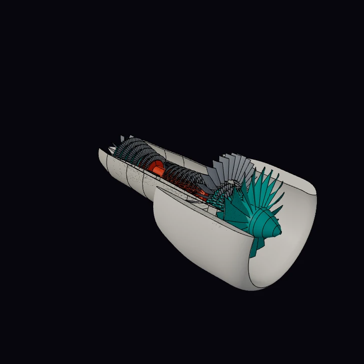 Turbofan Jet Engine (cutaway)A two-spool high-bypass turbofan in cutaway: nacelle, 20-blade fan, booster, 9-stage high-pressure compressor, annular combustor, high- and low-pressure turbines, rear frame and exhaust plug. A display model, not an engineered design. More than 1,800 spline-lofted aerofoils, with the casings opened by a boolean cut.
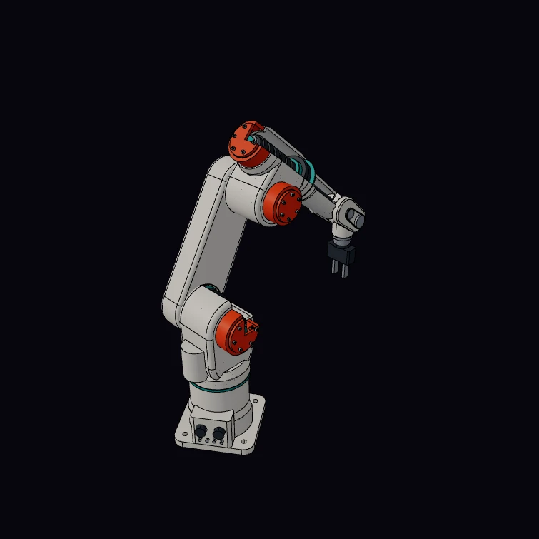 Six-Axis Robot Arm (cutaway)A six-axis industrial arm of the 3 kg, 580 mm class in cutaway. The joint layout is a published Denavit-Hartenberg table, and forwardKinematics() places every link from six joint angles. The housings are a display model: a boolean cut opens four of them to show illustrative servo drives with strain-wave reducers. The screws are M4 socket head cap screws to ISO 4762, and the cut shows two of them in their threaded holes.
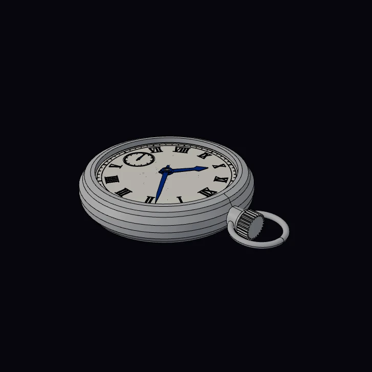 Pocket WatchAn open-face pocket watch with a hand-wound movement of the 16.5 ligne class: 36.6 mm, 17 jewels, 18,000 vibrations per hour. Each tooth count is from a published teardown, so the gear ratios are true, and the three hands show the time that the train gives them. The time parameter runs the watch. The screws have the miniature thread of ISO 1501, and in the exploded view each one turns out of its tapped hole. The bridges, the escapement shapes, the winding parts, the dial and the case are a display model.
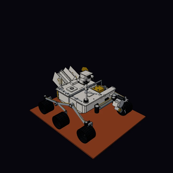 Mars RoverA six-wheel planetary rover of the 1-tonne class with a rocker-bogie suspension, in cutaway. The wheel size, the corner wheel positions, the deck height, the ground clearance, the mast height and the arm length are published figures. The kernel measures the volume of each part, and the example turns the volumes into a mass budget of 899 kg and a centre of mass. The arm parameter moves the arm, and the centre of mass moves with it. The screws are hexagon head screws M5, M6 and M8 to ISO 4017, each in a clearance hole and a tapped hole. The link lengths, the body layout and the equipment inside the body are a display model.
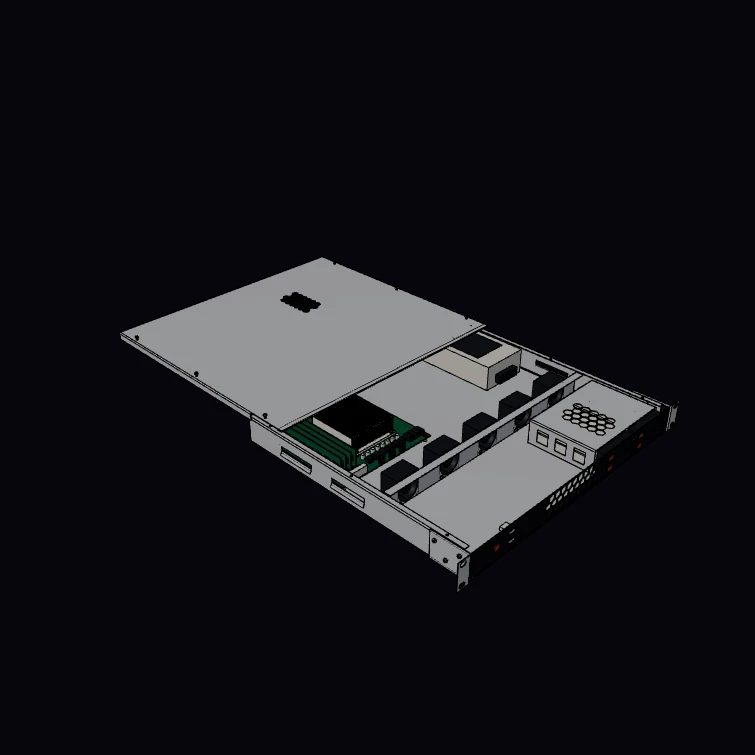 Server Chassis (1U)A 1U rack-mount server chassis for a 19-inch rack. Seven sheet-metal parts make the enclosure, and each one is a feature tree of bends and cutouts: the kernel folds it, unfolds it to a flat blank, and nests the blanks of four chassis on one stock sheet. The DXF button downloads that sheet. The rack dimensions, the fans, the drives, the board size, the power supply size and the M3 screws are published figures. The cover screws turn out of the tapped lips and stay in the thread of the cover. The layout, the vents and all small parts are a display model.
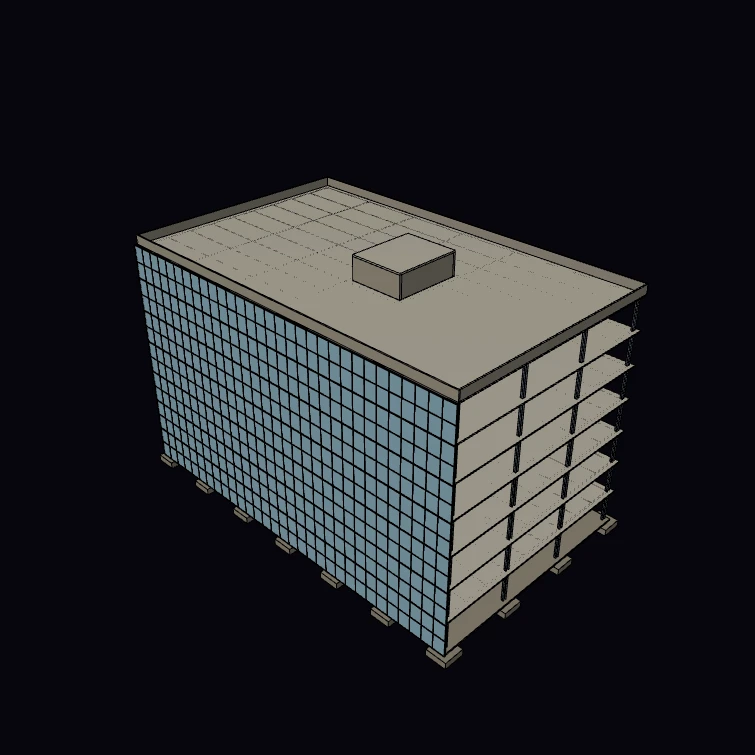 Office BuildingA steel-framed office building of seven storeys as a BIM model. Each column, beam, slab, wall, stair, door and curtain wall is a typed element in a storey, so the kernel takes off the steel and the concrete, and the Files button saves the IFC file. The steel sections, the planning grid, the storey height, the slab depth, the stair and the facade module are published figures. The core layout, the foundations and the roof are a display model.
Basics
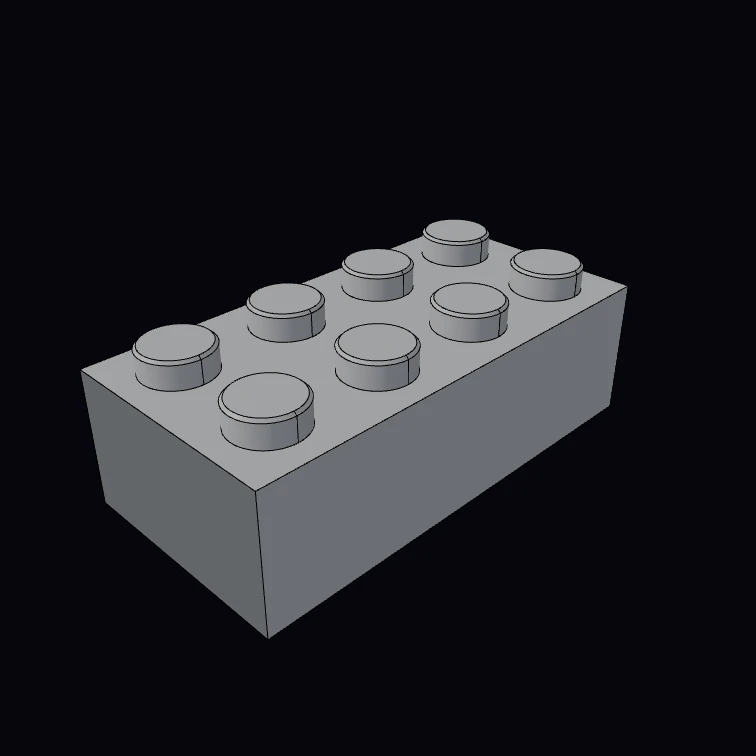 Stud brickParametric interlocking brick — any size from 3 numbers.
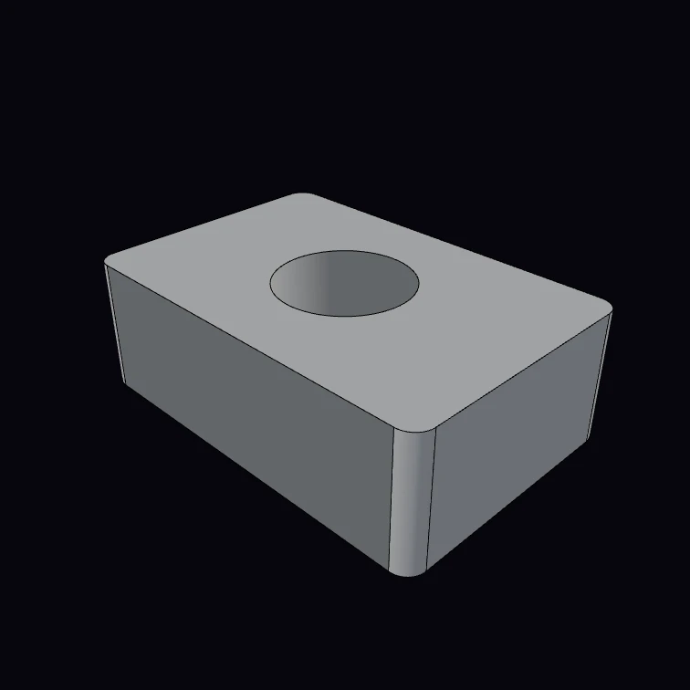 Drilled bracket (5 lines)Box, drilled and filleted — the canonical loop.
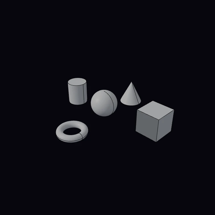 Primitives showcaseSphere, box, cylinder, cone and torus in a plus.
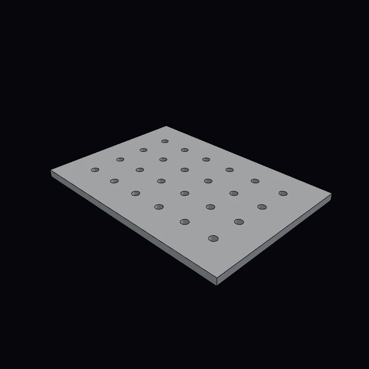 Parametric pegboardA cols × rows grid of pegs cut from a plate.
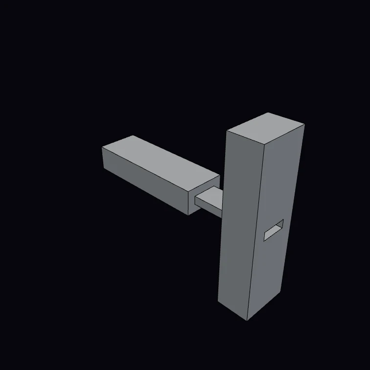 Mortise & tenonA through mortise-and-tenon joint, exploded.
Mechanical
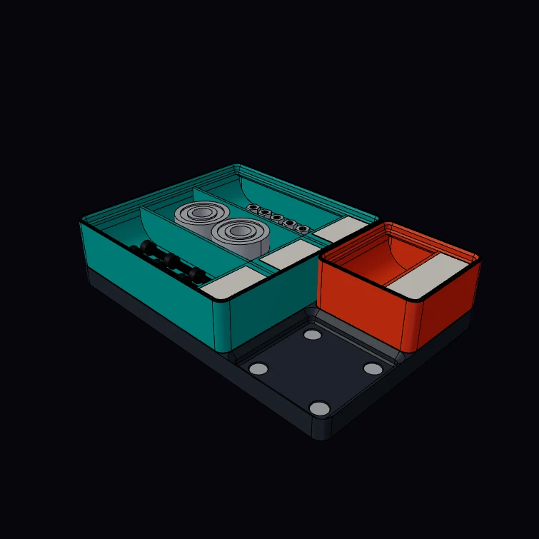 Gridfinity BinA Gridfinity bin with dividers, label tabs and a scoop, on a section of magnet baseplate with a second bin and one free socket. The 42 mm grid, the 7 mm height unit, the foot, socket and stacking lip profiles, the magnet and screw holes and the M3 thread are published figures. The loose screws and nuts in the bays have true helical threads. The kernel measures the size of the bin and its plastic volume. The walls, the tabs, the scoop, the labels and the hardware in the bays are a display model.
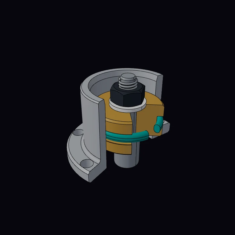 O-Ring in a Piston Gland (cutaway)An AS568 nitrile O-ring in a static piston gland, in cutaway. The ring sizes and the gland depth, width, clearance and corner radius are published figures. The kernel measures the rubber volume, and from it the stretch, the squeeze and the gland fill. The barrel, the piston body, the rod and the nut are a display model.
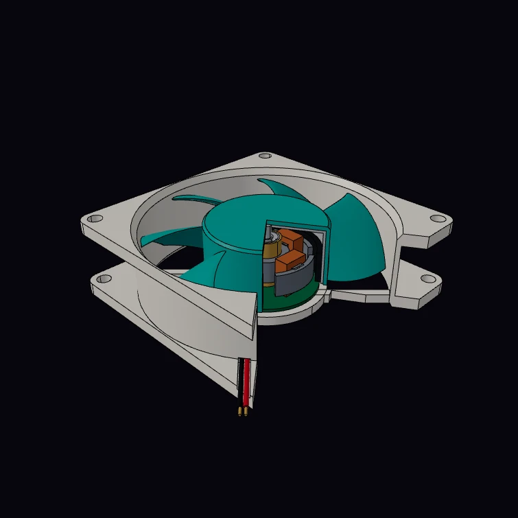 Axial Cooling Fan (80 x 80 x 25, cutaway)An 80 x 80 x 25 mm brushless axial fan in cutaway: flanged frame, seven lofted aerofoil blades, and the outer-rotor motor with its ring magnet, four wound poles, bearing tube and two ball bearings. The frame size, the 71.5 mm hole pitch and the 82 g mass are published figures. The kernel measures the mass from the solid volumes. The blades, the motor and the leads are a display model.
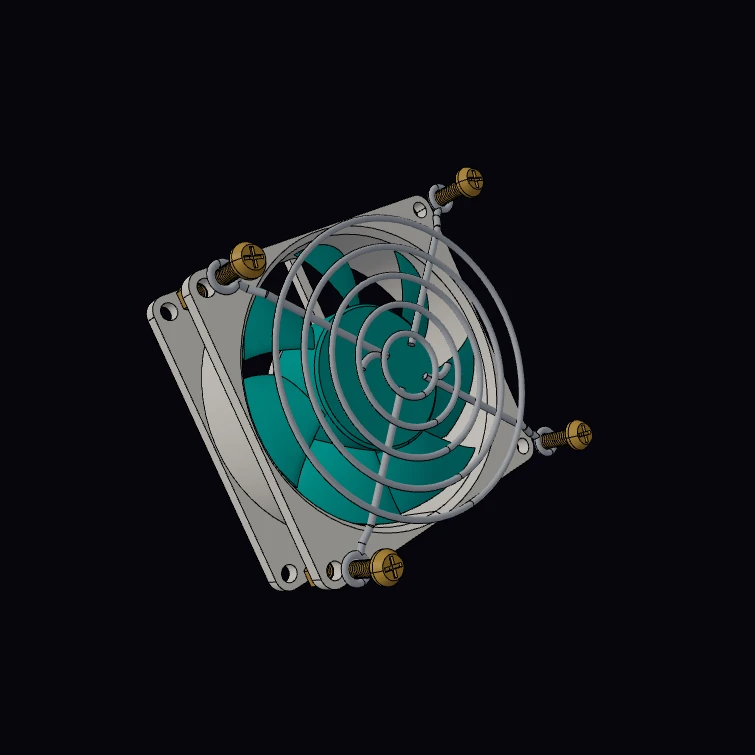 Wire Fan Guard (80 mm)A wire-form finger guard for an 80 mm fan: five welded rings on two bent ribs that end in mounting eyes, lifted off the fan with its four M4 pan-head screws. Each screw has a true helical thread and a nut behind the fan flange, and it turns once for each 0.7 mm that it backs out. The wire diameters, the 76.2 mm outside diameter, the eye pitch, the height and the M4 thread are published figures. The kernel measures the steel mass, and the ring gap is compared with the 12 mm test finger. The ring count, the rib path, the screw length and the fan are a display model.
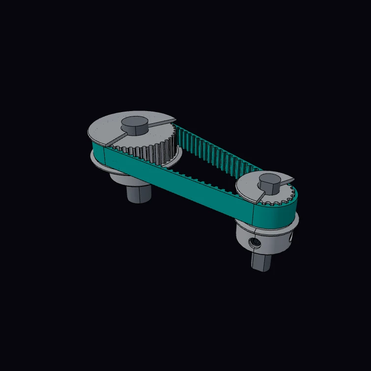 GT2 Timing Pulley and BeltA 20-tooth GT2 pulley on a closed 80-tooth belt that drives a 40-tooth pulley. The 2 mm pitch, the pitch-line offset and the three-arc groove form are published figures. The kernel measures the pitch line, which must equal the belt length. The flanges, the hubs, the set screws and the shafts are a display model.
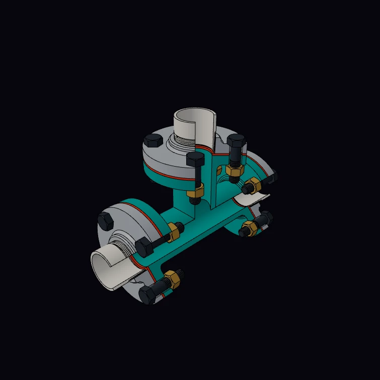 Flanged Pipe TeeA Class 125 ductile iron flanged tee, NPS 2, bolted to three threaded companion flanges with full face gaskets and hex bolts, and opened by a boolean cut. The bolts and nuts have a true 5/8-11 UNC helix, and each pipe turns into its flange on a taper pipe thread. The centre to face length, the wall, the flange drilling, the bolt size, the thread pitches and the weight are published figures. The kernel measures the volume of the tee: 17.2 lb of iron against 20 lb in the catalogue. The fillets, the gaskets, the hex sizes and the pipe stubs are a display model.
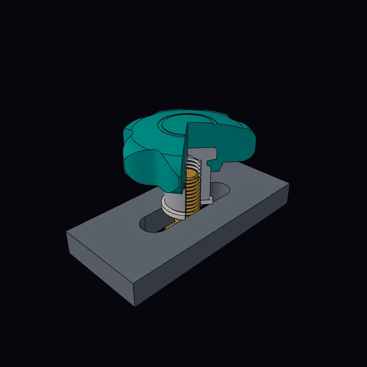 Fluted Star KnobA fluted star knob with a moulded-in steel hub and a tapped blind bore, on a hex screw that clamps a slotted bar, opened by a boolean cut. The grip diameter, the heights, the hub diameter, the thread and its depth are datasheet figures for four sizes. The flute outline, the hub anchor, the screw, the washer and the bar are a display model.
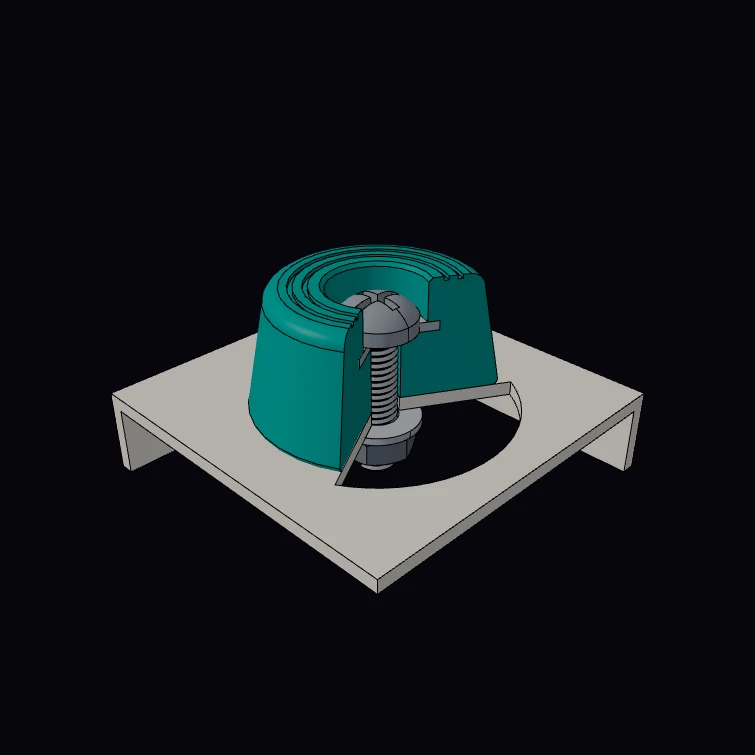 Rubber Foot on a Chassis (cutaway)A recessed rubber foot with a moulded-in steel washer, held to a chassis corner by an M4 screw, in cutaway. The foot diameter, height, recess and hole, and the M4 screw, nut and washer are published figures. The kernel measures the rubber volume. The taper, the washer in the rubber, the tread rings and the chassis are a display model.
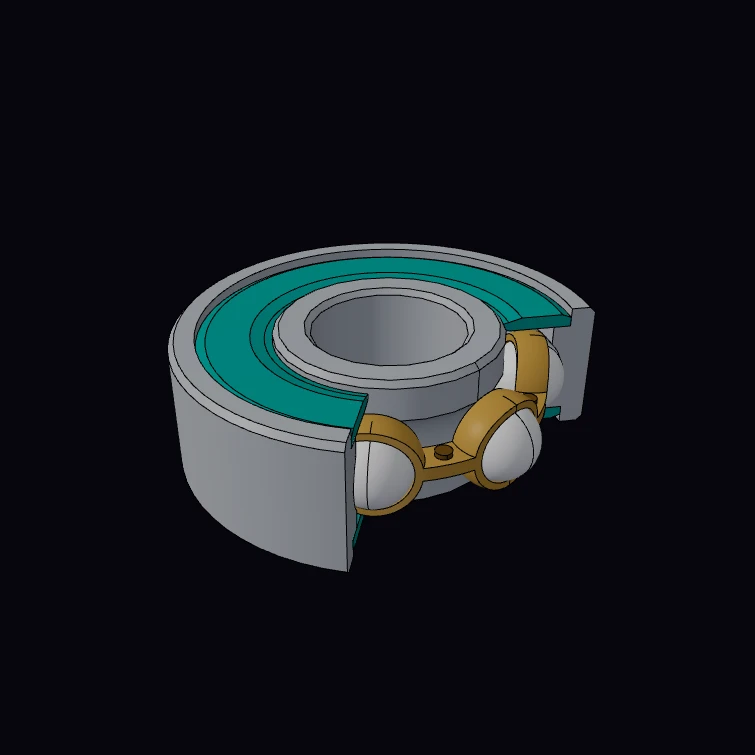 Ball Bearing (608, cutaway)A 608 deep-groove ball bearing with two rubber seals, in cutaway: two chamfered rings with raceways, seven balls, a riveted cage and the seal lips. The boundary dimensions, the ball set and the mass are published figures, and the kernel volumes give the mass for comparison. The shoulders, the cage and the seals are a display model.
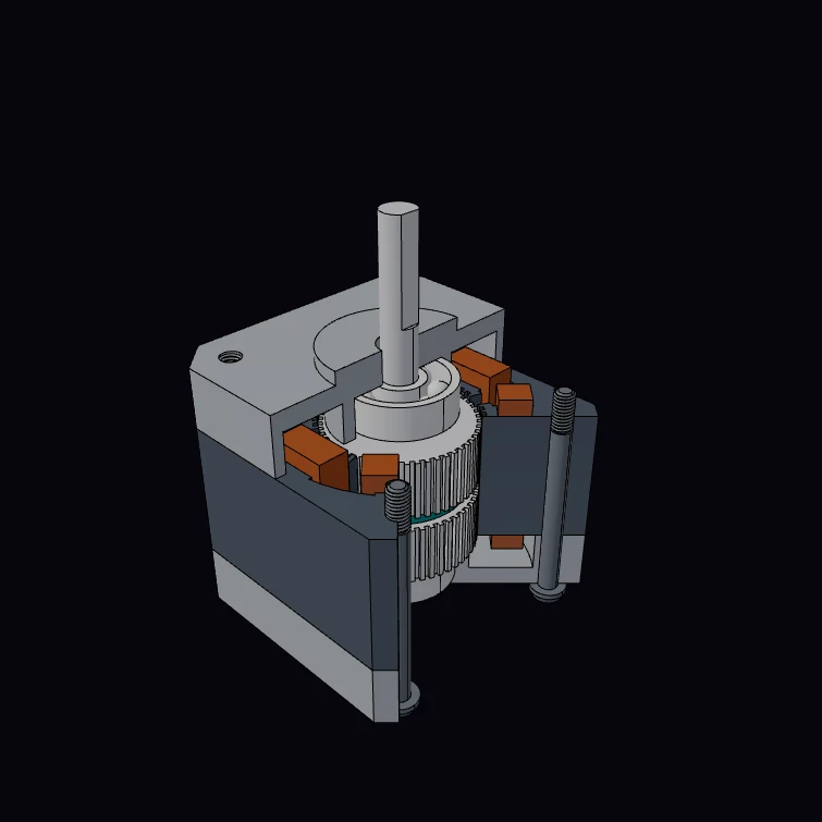 NEMA 17 Stepper Motor (cutaway)A NEMA 17 hybrid stepper motor in cutaway: toothed stator with eight wound poles, two 50-tooth rotor cups half a tooth apart on a disc magnet, ball bearings, end caps, through screws and connector. The mounting dimensions, the tooth and pole counts and the catalogue masses are published figures, and the 1.8 degree step follows from the tooth counts. The kernel measures the mass from the solid volumes. The lamination shape, the coils, the bearings and the end caps are a display model.
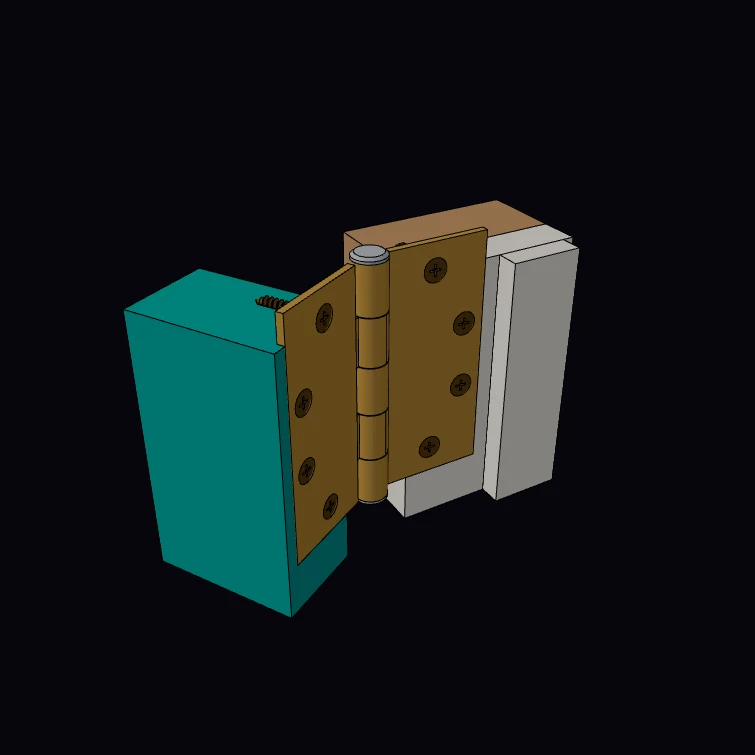 Butt Hinge on a DoorA 4-1/2 x 4-1/2 in full-mortise butt hinge of standard weight, on a door edge and its frame, with eight No. 12 wood screws. The hinge size, the gauge, the knuckle diameter, the swage and the screw-hole pattern are the published template dimensions. Each screw has the published 11 threads per inch as a true helix, in the thread that it forms in the wood. The open parameter swings the door side about the pin. The pin, the thread depth, the door and the frame are a display model.
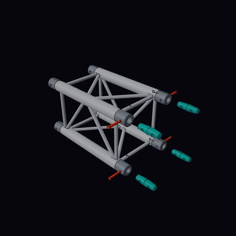 Square Stage TrussA 0.5 m segment of a 290 mm square stage truss with its four conical couplers, pins and clips pulled out. The section, the 50 x 2 mm chords, the 16 x 2 mm braces, the alloy, the lengths and the masses are published figures. The kernel measures the chord section and the mass and prints them beside the catalogue values. The brace pattern, the receivers, the cones, the pins and the clips are a display model.
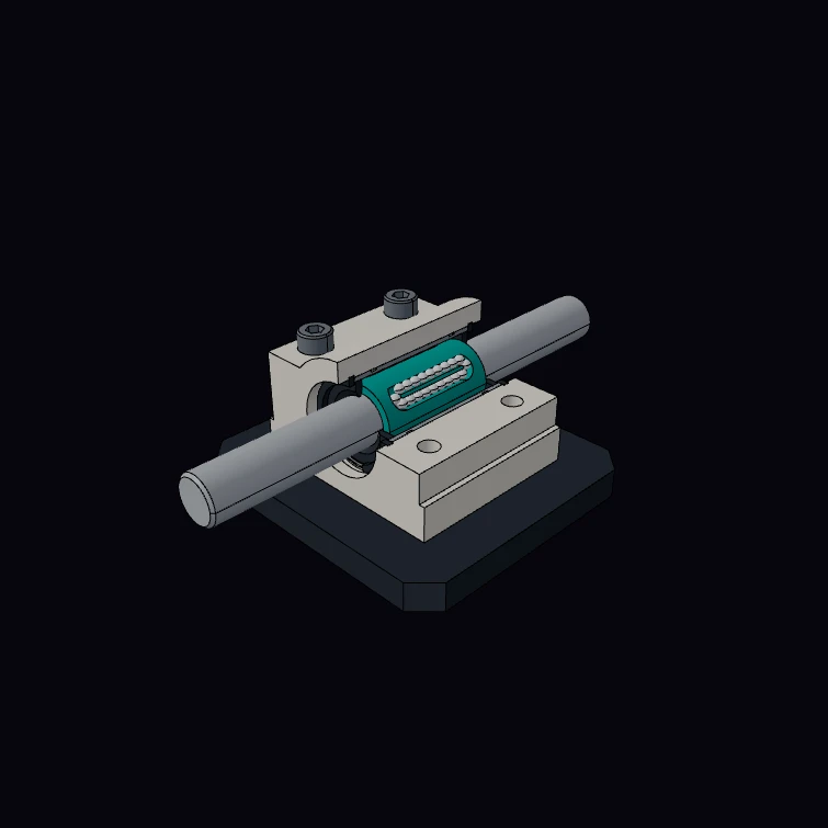 Linear Bearing Pillow Block (cutaway)A pillow block of the 8 mm class with its linear ball bushing on a shaft, in cutaway. The block and the bushing dimensions, the four ball rows, the mass and the M3 and M4 threads are published figures. The M3 cap screws are true helical screws in the tapped holes of the plate. The kernel measures the mass of the unit and of the bushing from the volumes. The ball circuits, the retainer, the seals, the snap rings and the plate are a display model.
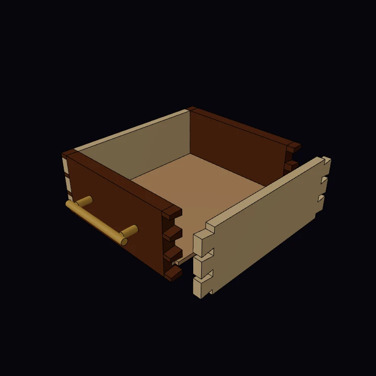 Dovetailed DrawerA small drawer with a through-dovetail joint on each corner: the sides carry the tails, the front and the back carry the pins. The slope follows the published rule, 1:6 for softwood and 1:8 for hardwood. The kernel measures the gap in a closed corner from the volumes of the two boards. The drawer size, the board thicknesses, the bottom panel and the pull are a display model.
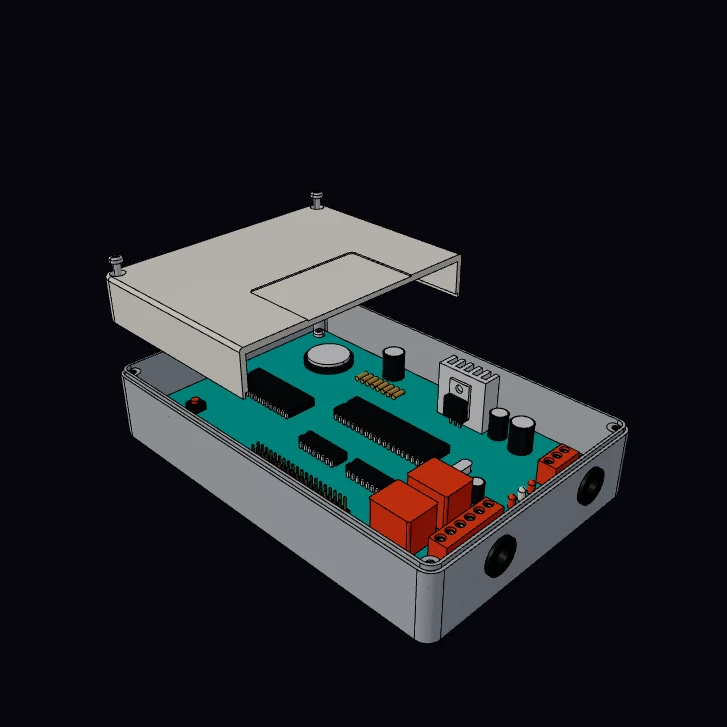 Two-Part Project EnclosureAn ABS project box with a Eurocard controller board on hex standoffs: chips, relays, terminal blocks, a heat sink and a coin cell. The four M3 lid screws turn out of their tapped posts, one turn for each pitch, as the lid lifts, and a cutaway opens the lid. The board size, the 2.54 mm lead grid, the M3 screws with their thread and the CR2032 cell are published figures. The kernel measures the mass of the two ABS shells. The box and the parts on the board are a display model.
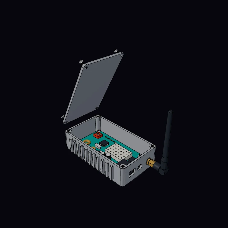 RF Transmitter EnclosureA finned die-cast aluminium transmitter box with its radio board, shield can and three connectors on one end wall: an antenna jack with a quarter-wave whip, a coaxial power jack and a six-contact data jack. The 1/4-36 antenna thread, the 5/16 in nut, the 5.5 x 2.1 mm power plug and the M3 screws are published figures, and the band sets the whip length. Each thread is a true helix in its mating thread, and the lid screws turn out of their bosses before the lid swings up. The kernel measures the mass of the box and the lid. The box and the board are a display model.
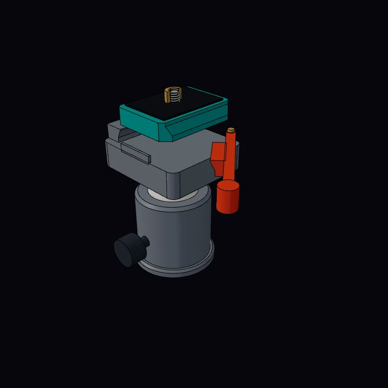 Quick-Release Camera PlateA quick-release camera plate of the RC2 type in the lever clamp of a ball head. The plate size, its mass and the 1/4-20 camera screw are published figures. The screw is a true helix in the tripod bush of a camera, and the bush is cut in half to show the two threads in mesh. The kernel measures the mass of the plate with its screw and pad and prints it beside the catalogue value. The dovetail section, the pockets under the plate, the clamp, the lever and the ball head are a display model.
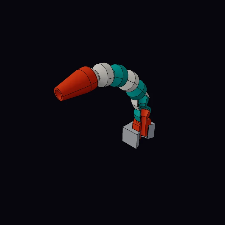 Modular Coolant HoseA modular coolant hose of the 1/4 inch system: ball-and-socket segments that snap together, from a threaded connector in a block to a round nozzle. A boolean cut opens the connector and the first two segments to show the joints, and the 1/4-18 taper pipe thread of the connector in the mating thread of the block. The bend parameter turns each joint about the centre of its ball. The pipe thread is the published one. All other dimensions are a display model, close to the sizes that sellers list for this system.
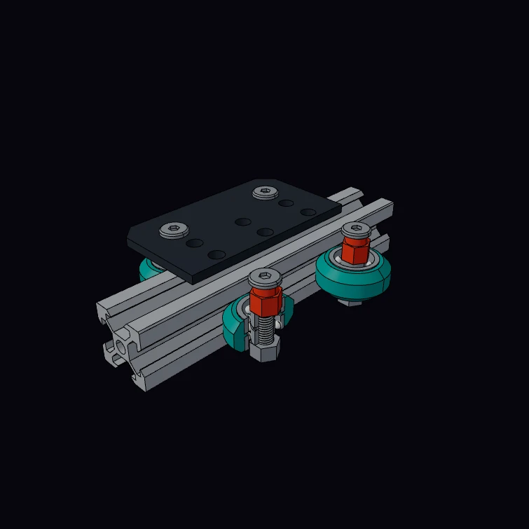 V-Groove Slider Rail and CarriageA 20 x 20 slotted rail with a carriage on four V-wheels, one wheel in cutaway. The rail size and mass, the wheel, the 625 bearings, the eccentric spacers, the plate size and the M5 thread are published figures. Each M5 screw is a true helix in the mating thread of its lock nut. The kernel measures the rail mass for each metre from its section. The inside of the slots, the wheel tip, the ball sets and the hole pattern are a display model.
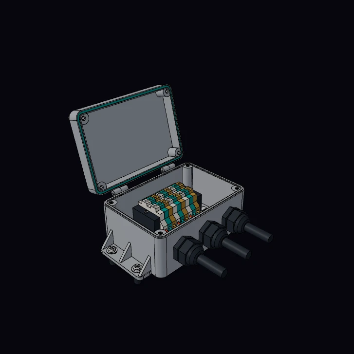 Wall-Mount Flanged Junction BoxA polycarbonate junction box with slotted wall flanges, a hinged lid with a gasket in its groove, M20 cable glands and a row of terminals on a top-hat rail. The M20 x 1.5 gland thread and its 24 mm hexagon, the 35 x 7.5 mm rail section and the M4 and M3 screw threads are published figures. Each thread is a true helix in its mating thread, and the captive lid screws are backed out of their posts when the lid is open. The kernel measures the mass of the base and the lid. The box, the hinge, the wall anchors, the terminals and the wiring are a display model.
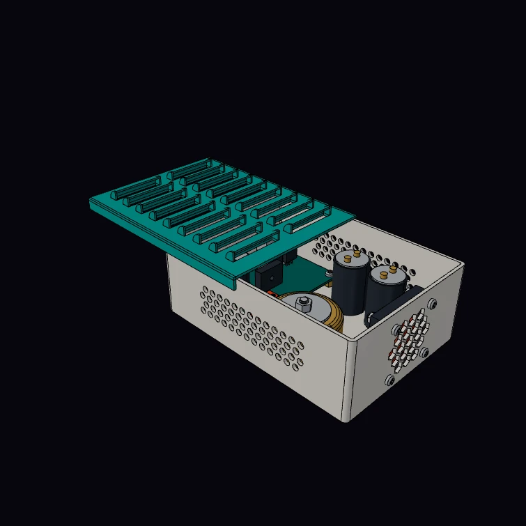 Vented Louvre Instrument CaseAn instrument case for a small linear power supply: a sliding cover with formed louvres, perforated side walls and a 40 mm fan behind a honeycomb grille. Inside are a toroidal transformer, two can capacitors and a regulator board. The fan frame and its 32 mm hole pitch, the M3 and M5 screw threads and heads and the open-area formula for round holes on 60 degree centres are published figures. Each screw has a helical thread in a mating nut, standoff or tapped hole. The kernel measures the open area of the side vents and prints it beside the formula. The case and the parts in it are a display model.
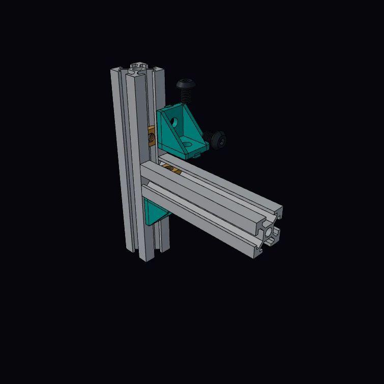 Corner Bracket on Slotted ProfilesTwo 20 x 20 slotted aluminium profiles joined by cast corner brackets with M5 screws and T-nuts. The upper bracket is exploded, the lower one is assembled. Each screw has a helical M5 x 0.8 thread that mates with the thread of its T-nut, and it turns one turn for each pitch as it backs out. The slot width, the slot depth, the bore, the web, the mass per metre, the bracket size and the thread are published figures. The kernel measures the mass per metre of the profile section. The cavity shape, the bracket walls and the T-nut body are a display model.
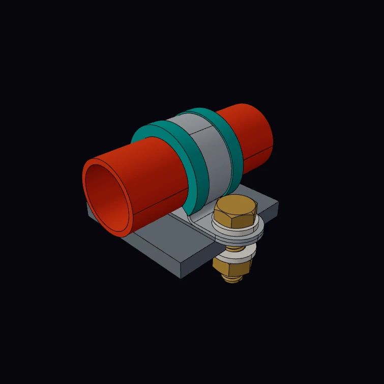 Rubber-Lined Pipe P-ClampA rubber-lined P-clip that holds a 20 mm tube on a mounting bar, with its hex screw, plain washers and nut. The bar ends on the screw axis, so the helical thread of the screw and the mating thread of the nut show in section. The band widths with their hole and screw sizes are datasheet figures, and the threads are metric coarse. The band thickness, the liner section, the bends, the screw length and the bar are a display model.
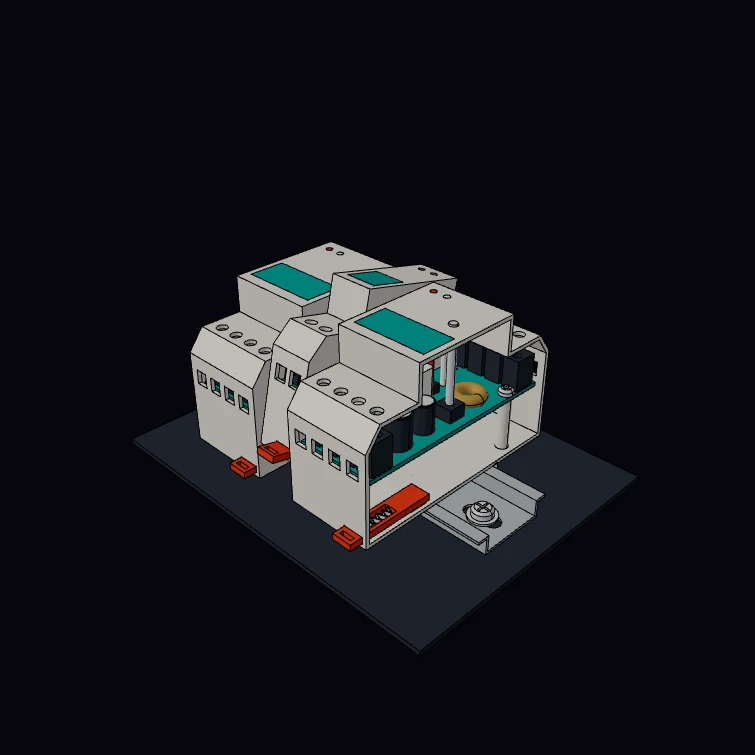 DIN-Rail Clip EnclosureThree modular enclosures on a perforated 35 mm top-hat rail. Each housing hooks on the upper rail flange, and a sprung slide latch grips the lower flange. The middle module swings off the rail with its latch pulled, and the right module is open to show its board, terminals, latch and spring. The rail section and slots, the 17.5 mm module width, the 45 mm front and the M3 and M4 screw threads and heads are published figures. Each screw has a helical thread in a mating thread: the rail screws in the plate, the board screws in their posts and the clamp screws in the terminal poles. The kernel measures the rail mass per metre against the catalogue figure. The housings, the latch and the electronics are a display model.
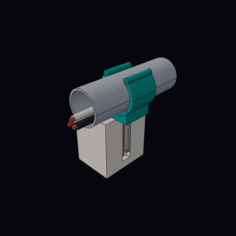 Conduit Snap ClipA snap clip that holds steel EMT conduit on a wall strip, with three wires in the conduit and the screw and wall plug shown in section. The wood screw has a helical thread with a 1.8 mm pitch that runs out on its cone point, and the plug has the mating thread that the screw forms in it. The outside diameter, the wall and the weight of the three trade sizes are published figures. The kernel measures the weight of the conduit for each metre. The clip, the screw, the plug, the wires and the wall strip are a display model.
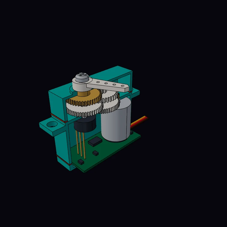 Hobby RC Servo (cutaway)A standard-size hobby RC servo with half of its case cut away: the four-stage involute gear train, motor, feedback potentiometer, control board, leads and horn. The body size and the tooth counts (10, 60/11, 49/11, 35/13, 42) are published figures, and the gears turn by their true ratios when the horn angle changes. The ratio from the tooth counts is compared with the stated 274.75 to 1. The horn screw is an M3 x 6 pan head screw with a helical thread in the tapped output shaft. The gear modules, the shaft positions, the motor, the board and the horn are a display model.
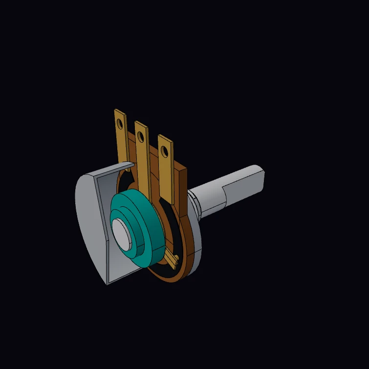 Rotary Potentiometer (24 mm, cutaway)A 24 mm panel-mount rotary potentiometer with its cover cut away: M8 x 0.75 bushing with a helical thread, washer and a nut with the mating thread, flatted shaft, phenolic wafer with the resistive track, rotor, wiper and three solder terminals. The body, bushing, shaft and terminal dimensions and the 300 degree travel are published figures, and the shaft angle moves the wiper. The kernel measures the share of the track between terminal 1 and the wiper. The wafer, the track, the rotor, the wiper and the cover tabs are a display model.
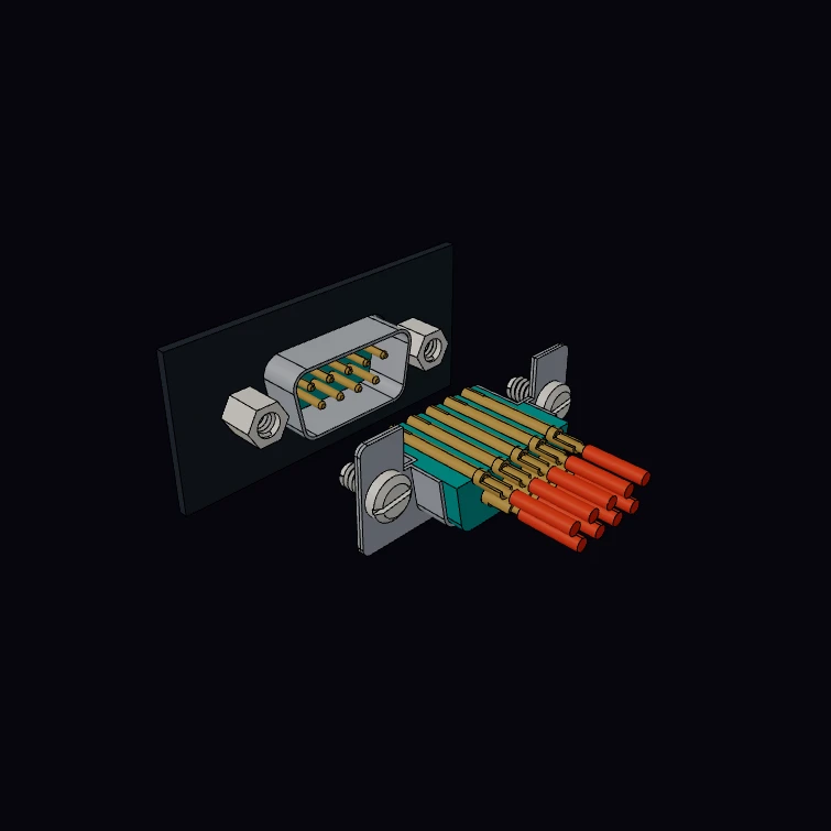 DE-9 D-Sub Connector PairA DE-9 pair before it mates: a panel plug with two jackposts, and a solder-cup socket with jackscrews and wires, cut open at its upper contact row. The flange, the two shell sizes, the 2.77 by 2.84 mm contact grid and the 4-40 UNC thread are published figures. The jackscrews, the jackposts and their nuts have helical threads, and each jackscrew turns one turn for each pitch as the pair mates. The kernel measures the clearance between the mated shells. The insulators, the contacts, the hardware and the panel are a display model.
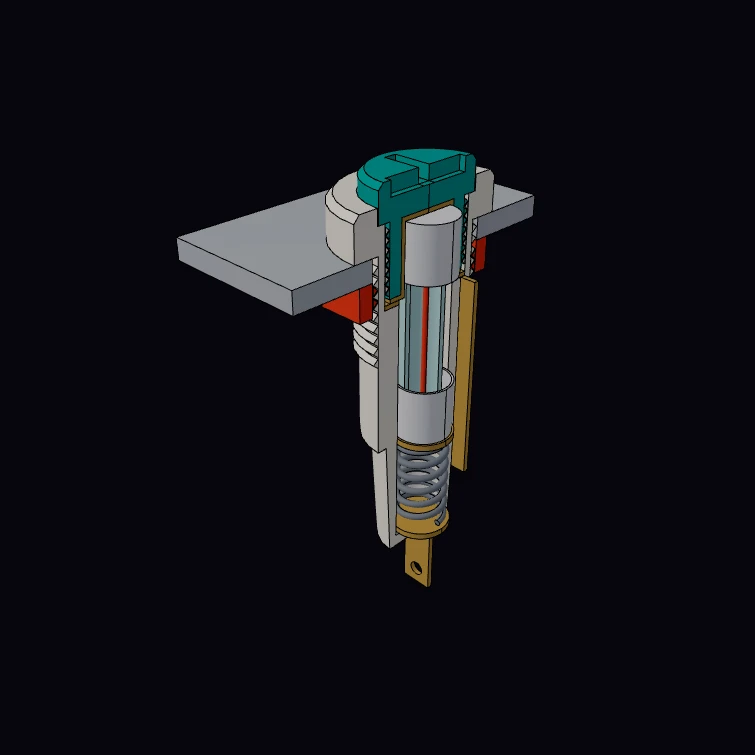 5 x 20 mm Panel Fuse HolderA low-profile panel fuse holder with its 5 x 20 mm fuse, in half section: screw cap, glass fuse with its element, contact sleeve, spring, solder terminals, panel and nut. The outline, the D-shaped panel hole, the terminals, the fuse and the three masses are published figures. The kernel measures the mass of the socket, the cap and the nut. The cap and the nut run on true helical threads: the cap turns once for each pitch as it comes out. The bores, the contacts, the spring and the two thread sizes are a display model.
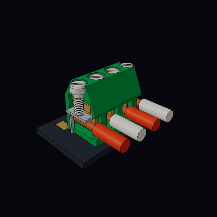 Green PCB Terminal BlockA green 5.08 mm rising-clamp terminal block on a board edge, with the two end poles in half section: screws, clamp cages, current bars, pins and 2.5 mm2 wires. The pitch, the body height and depth, the pins, the M2.5 screw thread and the wire size are published figures. Each screw is a true helix in the threaded top of its cage, and it turns once for each 0.45 mm that the clamp parameter lifts the cage. The kernel measures the body length against the pitch rule. The cages, the bars, the body cavities and the board are a display model.
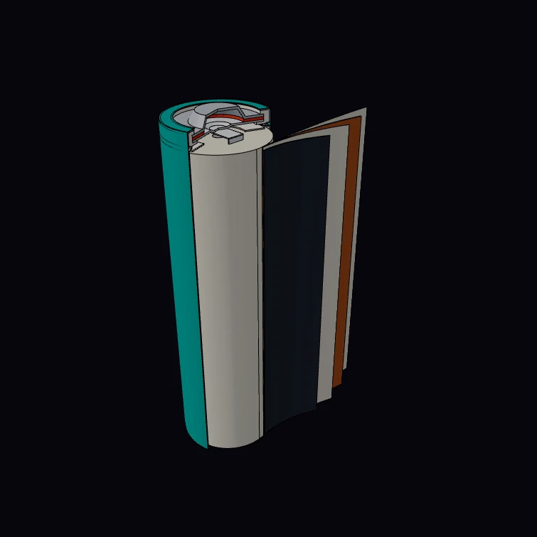 18650 Button-Top Battery CellAn 18650 lithium-ion cell with a button top, in cutaway: steel can with bead and crimp, jelly roll with its strips fanned out, tabs, insulators, gasket, vent disc, PTC ring, cap and wrap. The cell size, the can wall, the centre hole and the two electrode strips are published teardown figures. The kernel winds the 660 mm anode as a spiral and measures the roll diameter against the can bore. The fanned tail, the cap parts and the wrap are a display model.
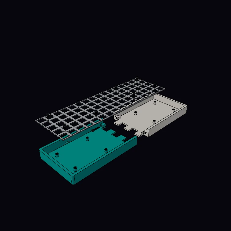 Finger-Tab Split JointA 3D-printed keyboard case that is too long for the print bed, cut in two across a comb of square fingers and screwed together through two lugs with brass inserts. The key pitch, the switch cutout, the plate thickness and the M3 thread are published figures. The screws and the inserts have true helical threads, and the explode parameter turns each screw once for each 0.5 mm that it comes out. The kernel bounds give the length of the whole case and of each half. The case, the 16 x 5 key grid, the fingers and the lugs are a display model.
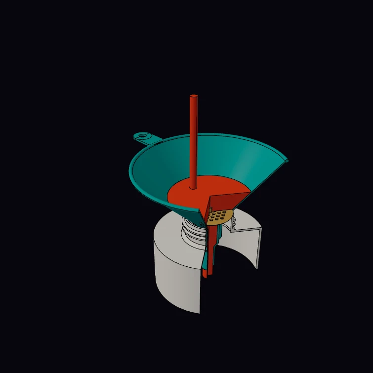 Pour Funnel With StrainerA 160 mm polypropylene pour funnel in use: rolled rim, hang tab, anti-airlock ribs, a two-step spout and a removable strainer, seated in the threaded neck of a canister and opened by a boolean cut. The funnel diameters, the material, the catalogue weights and the S 60/61 neck thread are published figures: the thread is a true helix of 6 mm pitch. The kernel measures the volume of the funnel and the strainer: 58 g of polypropylene against about 65 g in the catalogue. The wall, the spout, the ribs, the strainer pattern, the canister and the liquid are a display model.
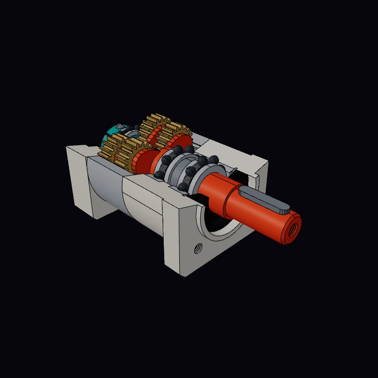 Planetary Gear Reducer (25:1)A two-stage 25:1 planetary gearbox for a NEMA 23 motor, in cutaway: each stage has a 12-tooth sun, three 18-tooth planets and a 48-tooth ring. The 60 mm frame, the lengths of the one-stage and two-stage units, the keyed 14 mm output shaft, the motor interface, the M5 threads and the bearing sizes are published figures. The input angle turns every gear by its tooth ratio, and the kernel measures the volume that the meshing teeth share (zero). The tapped holes and the clamp screw of the hub have true helical threads. The tooth counts and the parts inside the housing are a display model.
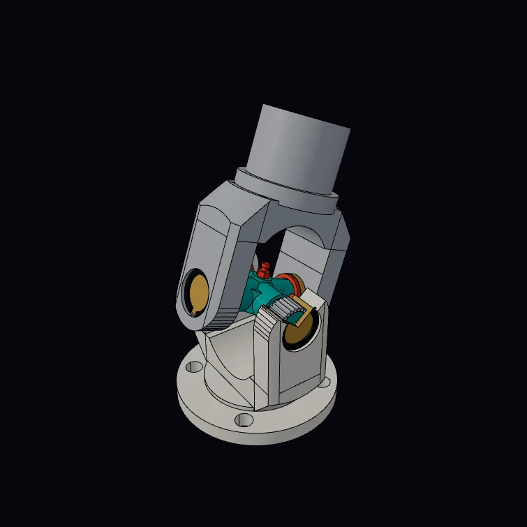 Cardan Universal JointA 1310 series universal joint of a propeller shaft: a cross with four needle bearing cups, seals and snap rings between a flange yoke and a tube yoke, with one ear cut open. The cup diameter, the span over the cups and the mass of the cross kit are published figures. The turn angle moves both yokes by the Cardan law, and the kernel measures the mass of the kit from its volumes. The trunnions, the needles, the seals and the yokes are a display model.
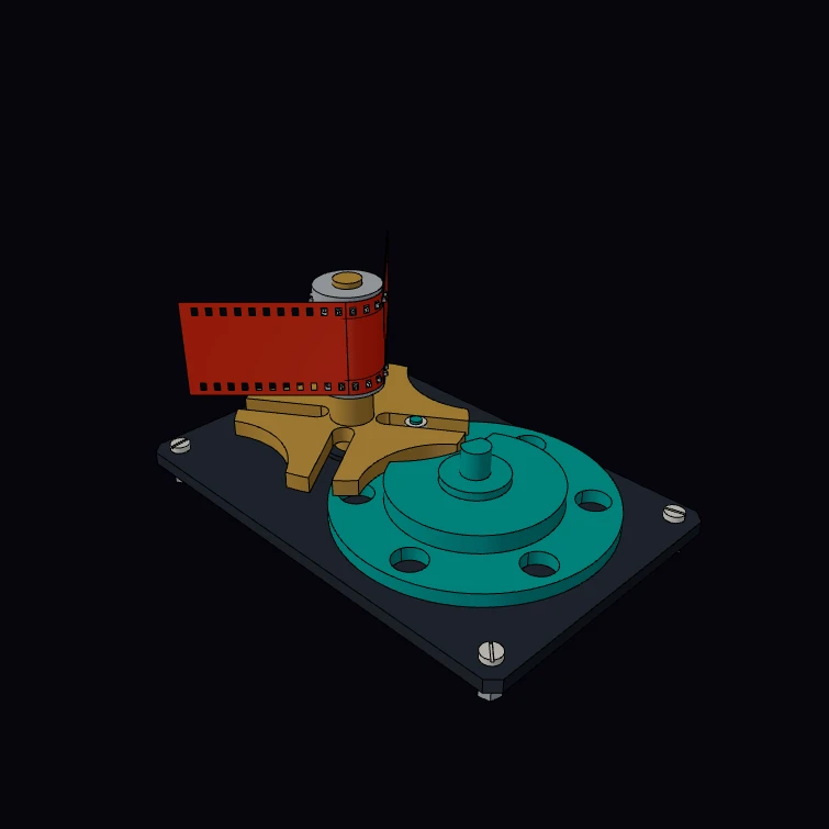 Geneva Wheel DriveThe Geneva drive of a 35 mm film projector: a driver with a roller pin and a locking cam indexes a four-slot star wheel, and the sprocket on the star shaft pulls the film down one frame for each turn. The film width, the perforation size and pitch, four perforations for each frame and the M4 thread of the plate screws are published figures. The turn angle moves the star wheel, the sprocket and the film by the Geneva law. The centre distance, the plate, its threaded standoffs and the part sections are a display model.
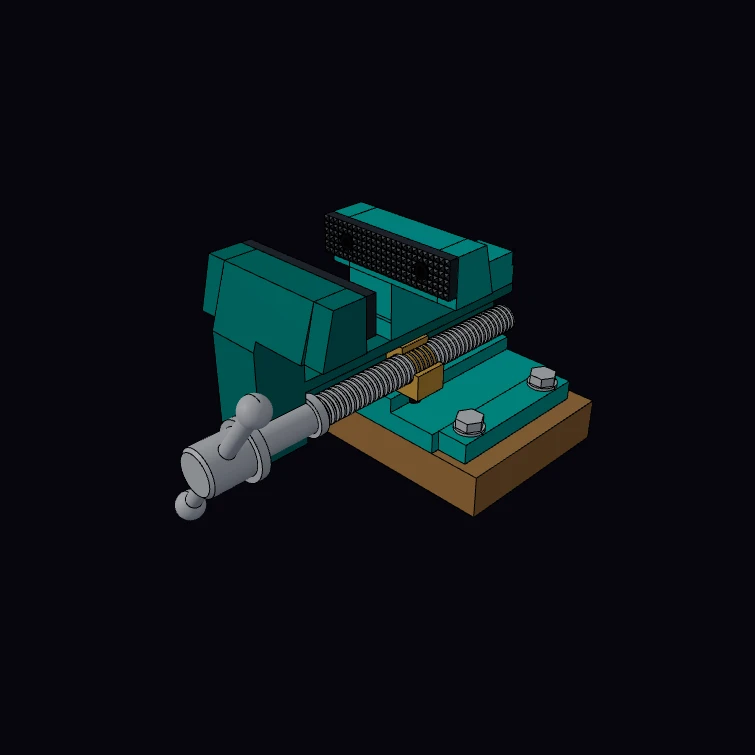 Machinist Bench ViseA 100 mm engineer's bench vise in cutaway, bolted to a piece of bench top. The Tr 20 x 4 screw thread, the fastener sizes and threads, the jaw width and the 9 kg catalogue mass are published figures. The turns parameter opens the jaw by one 4 mm pitch for each turn of the handle, and the kernel measures the mass from the part volumes. Every thread is a helix in its mating thread: the lead screw in the nut, the cap screws in tapped holes, the bench bolts in nuts. The castings, the nut, the jaw plates and the bench are a display model.
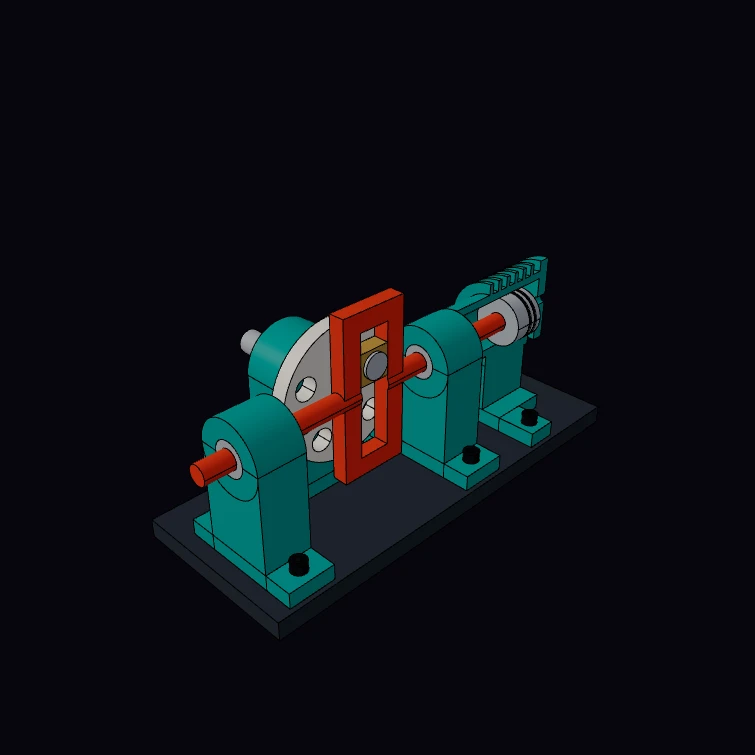 Scotch YokeA Scotch yoke that drives a piston in a cutaway cylinder. The crank pin carries a bronze block in the slot of the yoke, so the yoke and the piston move by the sine law: the throw times the cosine of the crank angle. The kernel bounds of the piston agree with that law. The 6202 bearings, the LM12 linear bushings and the M6 screws are published sizes: each screw is a true helix in a tapped hole of the base. The frame, the crank and the pump are a display model.
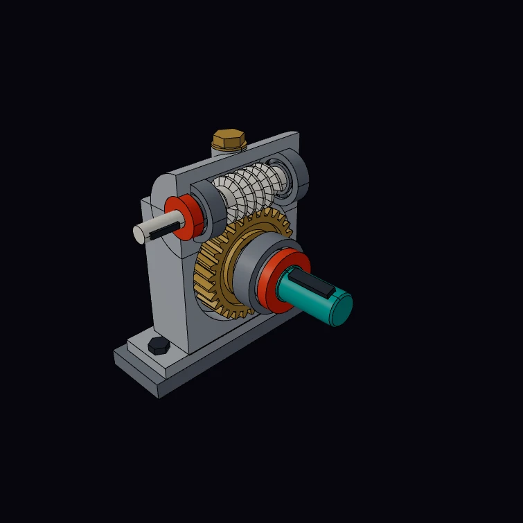 Worm Gear DriveA right-angle 30:1 worm gear reducer in a half housing: a one-start worm on two ball bearings above a helical bronze wheel, with keys, spacers and shaft seals. The module, the 20 degree pressure angle, the bearing sizes, the key sections and the screw threads are published figures. The foot screws and the filler plug have true helical threads in tapped holes. The turn angle moves the wheel by the tooth ratio, and the kernel measures the volume that the worm thread and the wheel teeth share (zero). The housing, the shafts, the bed and the tooth counts are a display model.
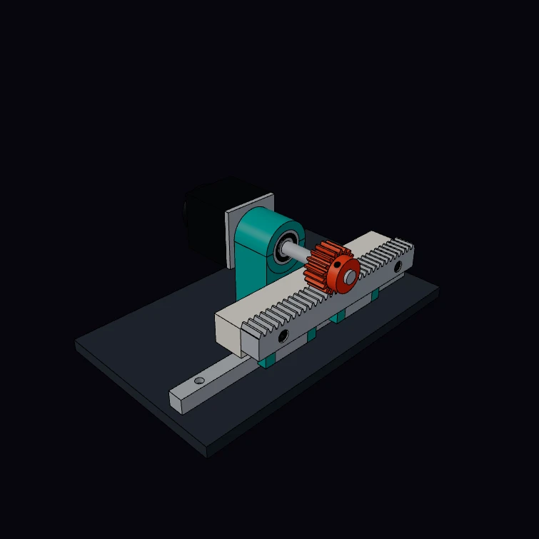 Rack & PinionA module 2 rack and pinion drive: an 18-tooth involute pinion in fixed bearings moves a rack on a linear guide by the pitch radius times the pinion angle, 113.1 mm for each turn. The gear, the rack section and its bolt holes, the size 15 guide, the 6201 bearings and the screw threads are catalogue sizes. The cap screws and the set screw have true helical threads in tapped holes. The kernel measures the pinion at 184 g against 190 g in the catalogue, and the full 80-tooth rack at 1.76 kg against 1.78 kg. The slide, the bearing stand and the motor are a display model.
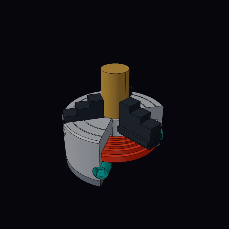 Self-Centering 3-Jaw ChuckA 100 mm self-centring scroll chuck in cutaway, with a bar in its jaws. The key turns a bevel pinion, the pinion turns the scroll, and the spiral rib moves the three jaws by one pitch for each turn of the scroll, so the keyTurns parameter sets the grip diameter. The outline, the centring recess, the tapped mounting holes with their helical M8 thread, the key square and the 3.3 kg catalogue mass are published figures, and the kernel measures 2.69 kg. The scroll, the bevel teeth and the jaws are a display model.
Sheet Metal
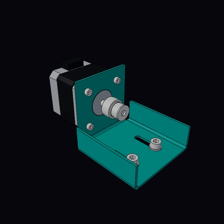 Mitered Motor BracketA mounting bracket for a NEMA 17 stepper motor, folded from one blank of 14 gauge steel: a face and two ribs fold up from the base, and each rib meets the face in a mitered corner. The gauge, the motor face, its hole pattern, its shaft and the screw threads are published figures. The M3 screws turn into the tapped holes of the motor and the M5 screws into nuts, with true helical threads. The kernel unfolds the bracket to the flat blank, with the bend allowance, and measures the mass. The motor and the pulley are a display model. The DXF button downloads the flat blank.
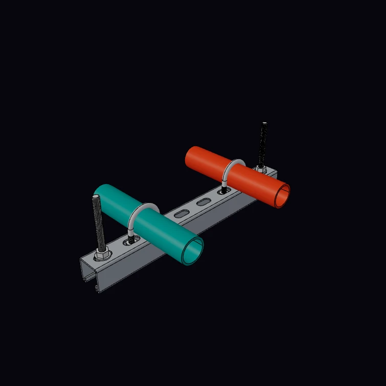 Slotted Strut ChannelA slotted strut channel, folded from one strip with six bends, as a trapeze hanger: two threaded rods carry it and two U-bolts hold a pipe each. The 41 mm section, the 2.5 mm gauge, the 14 x 28 mm slots at 50 mm, the mass for each metre and the M10 and M8 threads are published figures. The rods and the legs of the U-bolts have true helical threads, and each nut has the mating thread. The kernel unfolds the section to the flat strip and measures the mass. The lips, the pipes and the hardware are a display model. The DXF button downloads the flat strip.
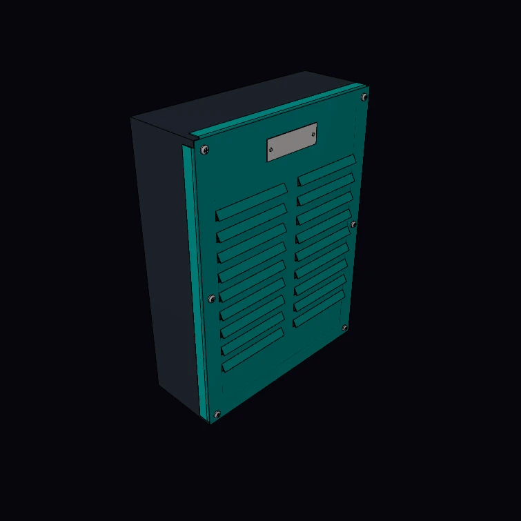 Louvered Enclosure CoverThe louvered cover of an equipment enclosure, from 20 gauge steel, with its screws, a name plate and the enclosure behind it. Each louver is a cut on three sides with the flap formed out along the fourth side, so the flat blank keeps all its material. The gauge and the screw threads are published figures. The M4 screws and the cable glands have true helical threads in tapped holes. The kernel unfolds the cover to the flat blank and measures its mass. The size, the louvers, the enclosure and the hardware are a display model. The DXF button downloads the flat blank.
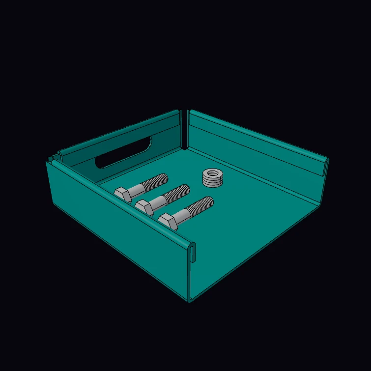 Hemmed Parts TrayA parts tray from 16 gauge steel with a hemmed safe edge, in cutaway: the top of each wall folds back on itself, and the cut shows the section of two hems. Set the type of the hem to closed, open, teardrop or rolled. The gauge and the M6 bolts with their helical thread are published figures. The kernel gives the sheet that one hem takes, unfolds the tray to the flat blank and measures its mass. The size, the handles, the feet and the hardware in the tray are a display model. The DXF button downloads the flat blank.
BIM
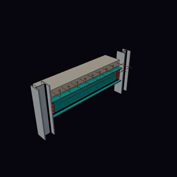 Steel Floor BeamA steel floor beam as a BIM model: an IfcBeam with a rolled I profile between two column stubs, with fin plates, bolts, shear studs and a strip of the slab with its mesh. The sections, the fin plate, the bolts, the studs and the mesh are published figures, and the kernel measures the mass of the beam for each metre against the section table. The view shows each M20 bolt as a screw with a helical thread in its nut, and the IFC file keeps it as a plain proxy. The span, the column stubs and the slab strip are a display model.
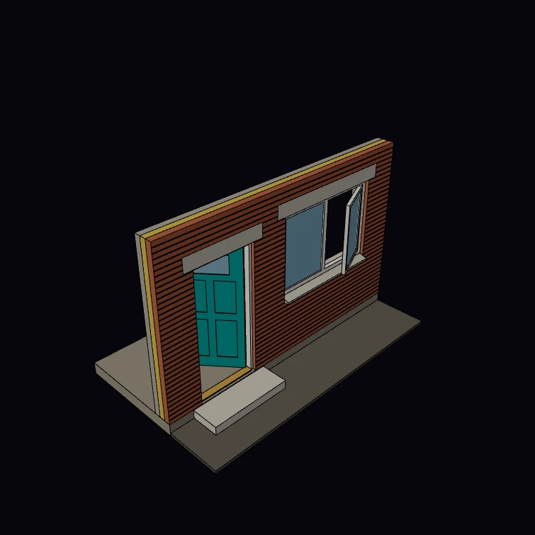 Wall with Door and WindowThe outer wall of a house as a BIM model: an IfcWall that hosts a door and a window in a project, site, building and storey structure. Each opening is a void that the model cuts into the wall solid, and the view shows the three layers of the cavity wall. The brick, the wall layers, the door leaf and the lintel bearing are published figures, and the kernel measures the wall volume against the box less the two voids. The openings, the window, the frames and the ground are a display model.
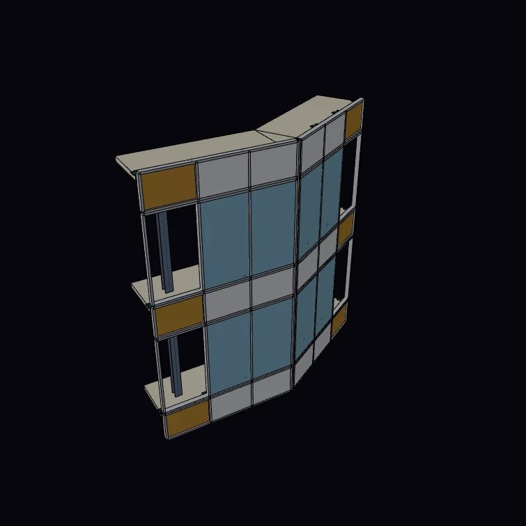 Curtain WallA curtain wall on a facade that turns a corner, as a BIM model. Each facet is a stack of IfcCurtainWall grids of glass panes between mullions and transoms, on its own wall line, and placedSolids() applies the two levels of the placement. The planning module, the storey height, the mullion and the glass unit are published figures, and the kernel measures the area of the vision glass. The slabs, the brackets, the back pans and the corner post are a display model.
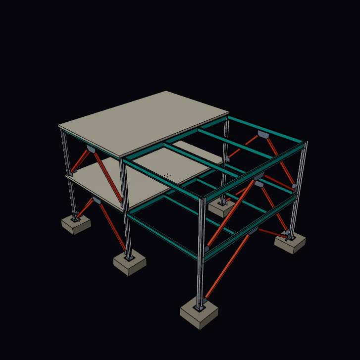 Braced Steel FrameA braced steel frame of two storeys as a BIM model: columns on a grid, a beam grid at each floor, tube bracing with gusset plates, a slab on each level and a base under each column, all grouped as one IfcElementAssembly. The sections, the grid, the storey height, the slab depth and the column base are published figures, and the kernel measures the mass of the steel against the section tables. The view shows each M24 holding down bolt as a screw with a helical thread in its nut, and the IFC file keeps it as a plain proxy. The layout of the bracing, the gussets and the footings are a display model.
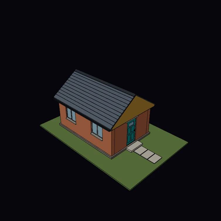 Building ShellA garden studio as a BIM model: a foundation slab, four walls that meet at the corners, a door and three windows, a gable roof on the wall heads and an IfcSpace for the room, in a project, site, building and storey structure. The brick, the wall layers, the door leaf, the lintel bearing, the step up from the ground and the least roof pitch are published figures, and the kernel measures the volume of the room. The plan, the windows and the trim are a display model.
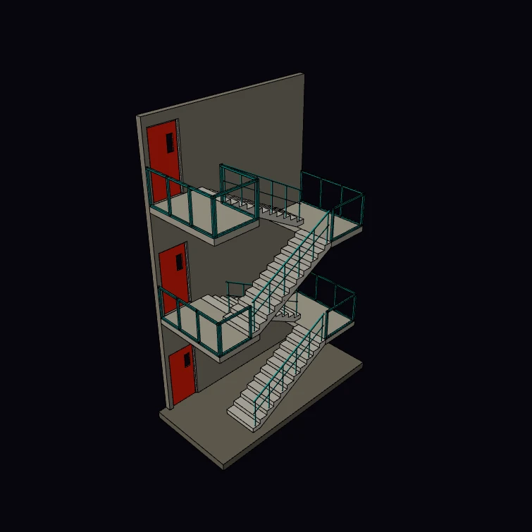 Switchback StairA stair core as a BIM model: a half-turn stair for each storey, with two flights that go opposite ways, a half landing at the turn, a wall with a door at each floor, railings on the landings and a balustrade along each flight. The stair is an IfcStair with no solid of its own, and placedSolids() gives its flights. The rise, the going, the flight length, the widths and the heights of handrail and guarding follow the limits of a building code for a general access stair, and the kernel measures the concrete. The wall, the doors and the shape of the balustrade are a display model.
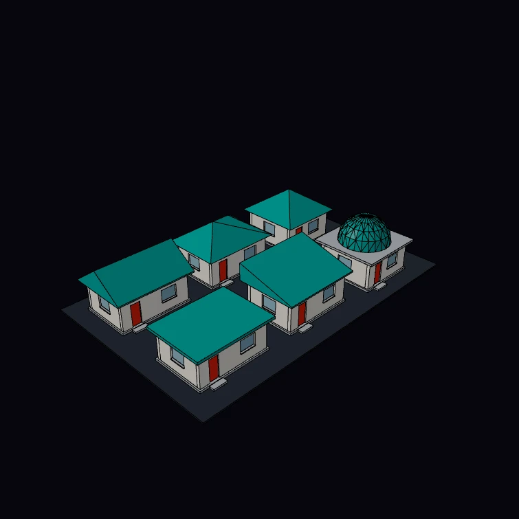 Roof GallerySix roofs of the brepjs-bim roof builder on six small pavilions: gable, hip, pyramid, flat, shed and dome. Each one is a real IfcRoof solid that one addRoof call shapes from its type and its pitch, and the IFC export writes each body. The 35 degree pitch is the published minimum for clay plain tiles. The kernel measures the tiled area of each roof: the gable and the hip have the same area. The pavilions are a display model.
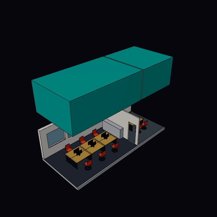 Space VolumeAn IfcSpace is the volume of a room, an element of its own that plain solid modelling does not have. Two rooms of an office floor, each with its space lifted out above it to show the volume as a solid: set lift to 0 to put it back. The kernel measures each volume, and the published rule of 11 cubic metres of room for each person gives the people that the room has volume for. The rooms and the furniture are a display model.
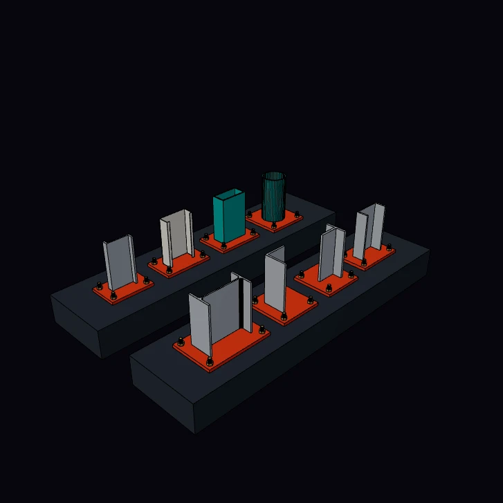 Profile GalleryEight structural sections as real IfcColumn stubs on bolted base plates: I, L, T, U, Z, C, rectangular hollow and circular hollow. Beams and columns share one profile vocabulary, and each named kind exports as its own parametric IFC profile def, so the section stays editable data downstream. The IPE 300, the angle, the UPE 200 and the two hollow sections have their published dimensions, and the kernel measures the mass of each metre to set against the steel table. The view shows each M20 holding-down bolt as a screw with a helical thread in its nut, and the IFC file keeps plain proxies. The tee, the zed, the lipped channel, the base plates and the trestles are a display model.
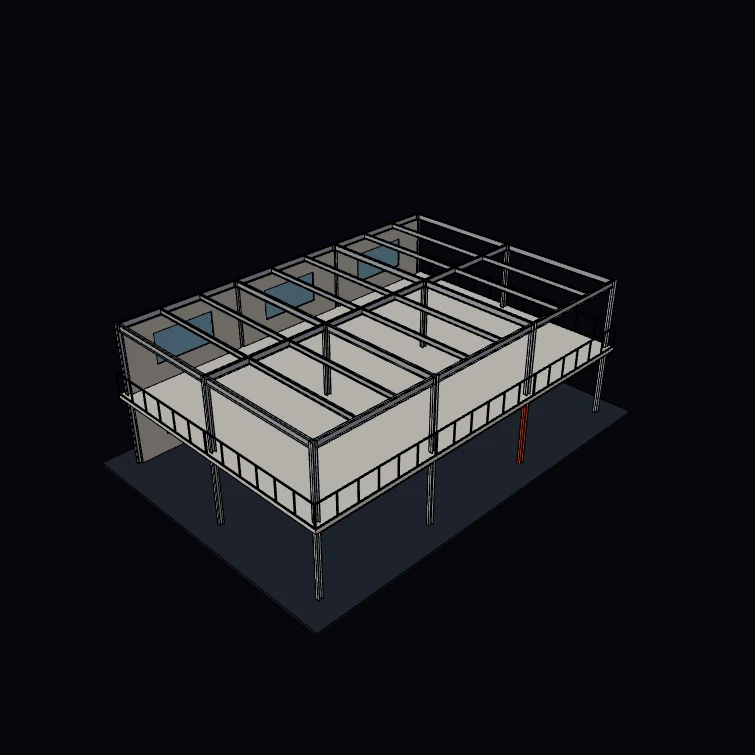 Validated ExportOne toIfcValidated call exports the model and runs the full set of checkers: referential integrity before the file is written, then schema, round trip, geometry validity and the buildingSMART gherkin rules. This steel-framed block has two faults on purpose. A column that is in no storey makes the integrity gate block the export: the view paints the column that the gate names in orange, and the code repairs it. A project with no coordinate reference system gives the GRF003 warning. The export runs against IFC4 and IFC4X3, and the Files button saves the full report. The sections are published sizes, and the block is a display model.
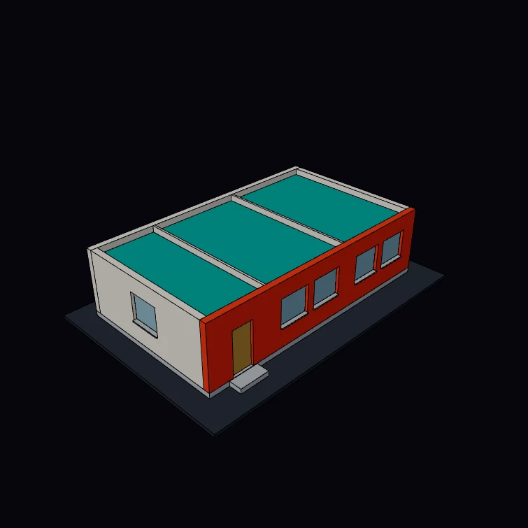 COBie, IDS and BCFThe three formats that carry the work around a model, as one chain on a small office block. COBie 2.4 handover sheets come from the spatial structure. An IDS 1.0 requirement is checked against the exported file, and the front wall fails it. A BCF 3.0 issue is then filed on that wall by its GlobalId, with a camera on it, and the view paints the wall orange. Results print to the console, and the Files button saves the COBie sheets and the BCF markup and viewpoint. The block is a display model, shown with its roof off.
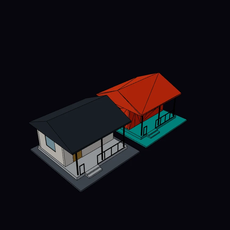 IFC Round TripExport a pavilion to IFC, read the file back with fromIfc, and show the source model and the model from the file side by side. Each solid of the second pavilion comes from the exported file, so a difference between the writer and the importer is visible. Its colour is the geometry fidelity of each element: teal for a parametric solid, orange for a mesh that the importer sewed into a solid. The console reports the fidelity counts, the GlobalIds that survived, and the largest volume difference that the kernel measures between a source body and its copy. The pavilion is a display model.
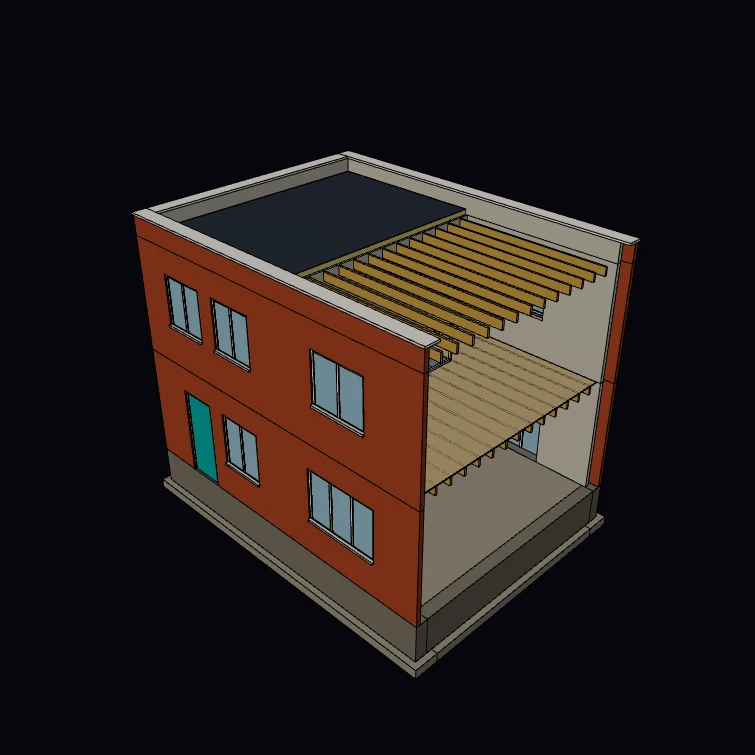 Quantity TakeoffA quantity schedule of a brick and block house shell, computed from the model: the kernel measures the net volume of each element after the openings are cut, and the schedule groups the volumes by category and material. The brick and block sizes, the joint and the stair limits are published figures, and the console compares the brick and block counts with the guide figures of 60 and 10 for each square metre. The plan, the openings, the joists and the roof are a display model. The Files button saves the schedule as CSV.
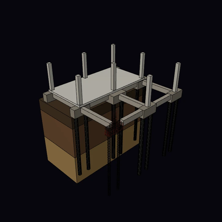 Piled FoundationsThe foundations of a concrete frame with the ground cut open: bored piles, pile caps, ground beams, columns and the suspended slab that they carry. Piles and footings are typed IFC elements (IfcPile, IfcFooting), so a structural model can schedule them. The pile spacing, the cap edge distance, the concrete cover and the guide rate for the steel in a cap are published figures, and the kernel measures the concrete of each class and the bars of one cap. The grid, the sizes, the strata and the cage are a display model.
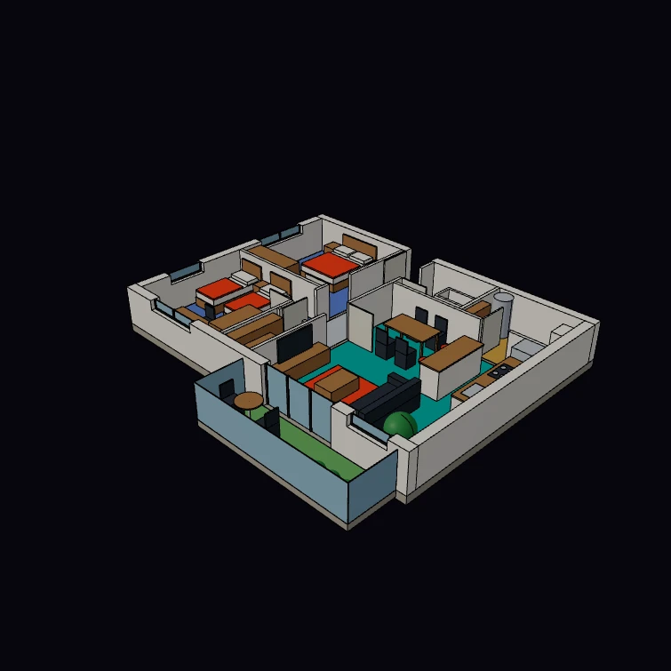 Room Schedule and ZonesThe room programme of a two-bedroom flat. Each room is an IfcSpace with a name, an area and a volume, and two sets of zones group the spaces: one by use and one by ventilation. The console prints the room schedule with the total of each zone, and compares the areas that the kernel measures with the published space standard for a flat of this size. The plan, the walls and the furniture are a display model.
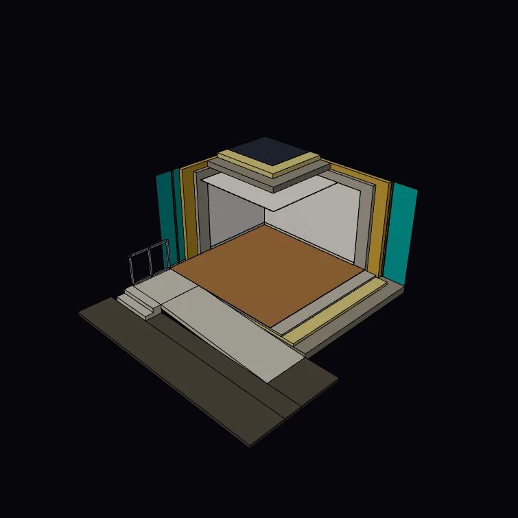 Finishes and AccessThe finishes of one corner of a building, cut back layer by layer: the floor, the walls, the ceiling and the roof are built up from separate IfcCovering elements, each with its own material and thickness on the slab or the wall that it covers. A 1:15 entrance ramp with a landing, two steps and a posted guardrail gives access. The ramp limits, the step rise, the conductivities and the U-value limits are published figures, and the kernel measures the area of each covering. The room and the build-ups are a display model.
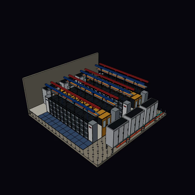 Datacenter HallA data hall designed on the 600 mm tile grid: four rows of 42U racks on the metric 8-tile pitch with hot-aisle containment, a fully perforated cold-aisle floor over a raised-floor plenum, six CRAH units sized N+1, and A+B power down redundant 250 A overhead busway. Each element carries datacenter psets (with the IFC class that a native writer would use) and is in a zone or a system. The console runs the capacity checks of a design review, and the Files button saves the equipment schedule. The view lifts the floor at one end to show the plenum. The rack fronts, the supports, the cables and the pipes are a display model.
Families
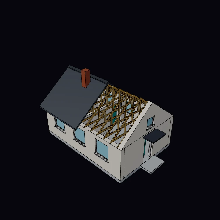 Declarative BuildingA small house authored as one tree of typed families: walls, gables, a floor slab, trussed rafters, a roof covering and a chimney stack. Each door and window is a fill-role element in the voids of its wall, so the tree holds a real opening with a Fills relationship, and its frame, glass and leaf are children that move with it. Each element has an order-independent key path, and the model is drawn by type from that index. The door leaf and the truss spacing are published figures. The plan, the walls, the windows and the roof are a display model.
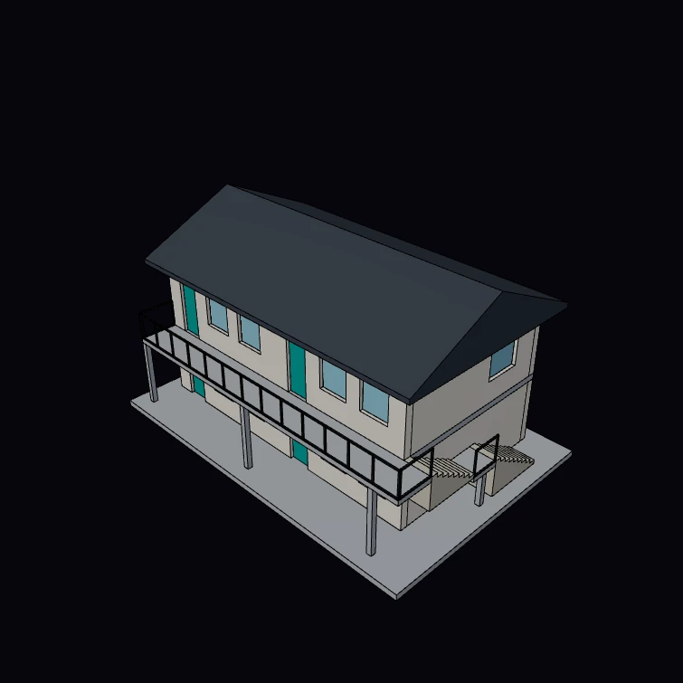 Families to IFCA block of flats on two storeys, authored as families and projected into a BimModel with familiesToBim: spatial containment, wall openings as IfcOpeningElement relationships with IfcDoor and IfcWindow fillers, and GlobalIds derived from key paths. The console shows that every GlobalId is the same after the tree is reversed. Families with no IFC mapping, the door leaves and the glass panes, go out as proxies. The BIM panel shows the spatial tree and the IFC button downloads the file. The stair rise, going and landing are published figures. The plan and the sizes are a display model.
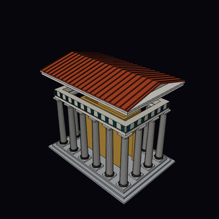 Shared MaterializationA Doric temple authored as a family tree: sixteen identical fluted columns and thirty-six triglyphs, each with its own key path. The CSG IR is content-addressed, so the evaluator builds one column and one triglyph for each facing, and a second evaluation with wider bays is almost all cache hits. The console shows the counts. The proportions of the order are published figures. The taper, the steps, the cella and the roof are a display model.
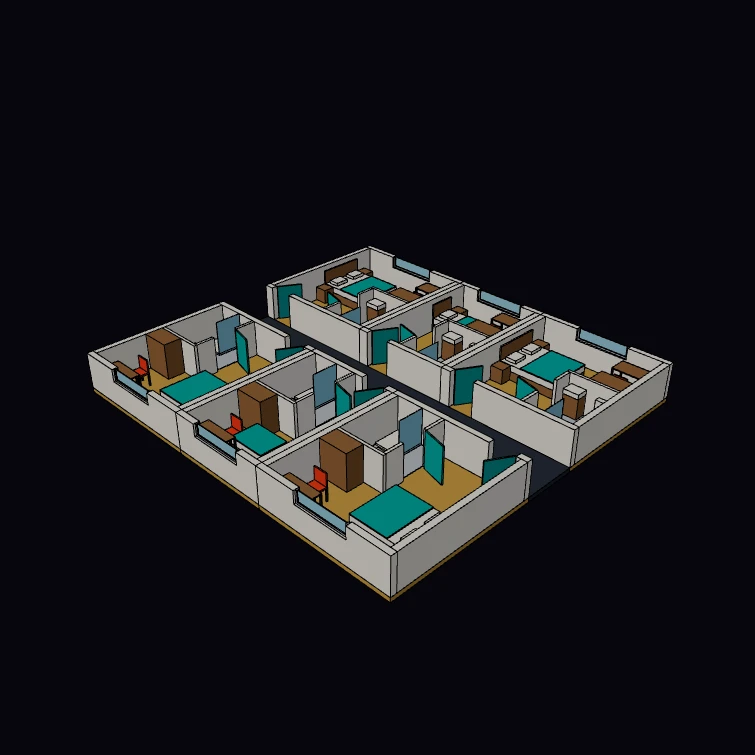 Room CompositionA floor of hotel rooms shown as a plan cut. Room is a family composed from Wall, Door and Window, with a Bath family and the furniture inside it, and its group transform places the whole room as a unit: the south row is the same family turned half a turn. Key paths nest through the composition, down to suite/n1/bath/west/voids:door/fill/leaf, and rooms of equal width share their recipes. The door leaf and the mattress sizes are published figures. The plan, the walls and the furniture are a display model.
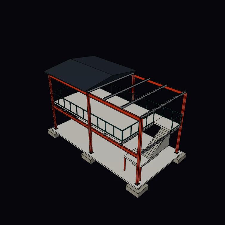 Declarative Steel FrameA steel frame on two storeys, authored as one tree of families and projected through familiesToBim: pad footings, HE 200 A columns, IPE 300 primary beams, IPE 200 joists and purlins, a deck, guard rails, a gable roof and a switchback stair in an open well. Each member has a GlobalId derived from its key path, so the order of the tree does not change the exported IFC. The kernel takes off the steel and compares it with the catalogue masses. The sections, their masses and the stair figures are published. The grid, the stacked framing, the deck and the roof are a display model.